CPA Stage 2 The draft network diagram
Activities
A network is made up of combination of activities, represented by arrows.
| ACTIVITY | = | an Arrow |
| START of the ACTIVITY | = | Tail of the arrow |
| FINISH of the ACTIVITY | = | Head of the arrow activity |
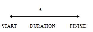

The length of the arrow is not related to the time of the activity.
Activities are usually represented in the diagram by a letter, e.g. activity A.
Events or nodes
Beginnings and ends of activities are represented as numbered circles called NODES.These are not related to time or resources. As we will see later these nodes contain information crucial for the project:
- The number of the activity
- The earliest time when the following activity can start
- The latest time that the previous activity can finish.
We will return to these later in this section.

Let's provide an illustration of a project where a firm is planning to test market of a particular new product. It has identified the activities and dependencies as follows:
Example 1: Hatfield Cosmetics - the test market
| Activity | Description | Preceding activity | Duration (days) |
|---|---|---|---|
| A | Decide test market area | None | 1 |
| B | Agree marketing strategy | None | 2 |
| C | Agree product specification | None | 3 |
| D | Decide brand name | B | 1 |
| E | Prepare advertising plan | A | 2 |
| F | Agree advertising package | E | 3 |
| G | Design packaging | D | 2 |
| H | Production of test batch | C | 5 |
| I | Pack and distribute | G, H | 10 |
| J | Monitor media support | F, D | 3 |
The first task is to produce a sketch, or 1st draft of the logic diagram. The important thing is to get all the dependencies shown above correctly reproduced in the diagram.
Figure 1 Draft CPA diagram
Note: The lines represent the activities. The description, or title of the activity, is usually written above the line, and its duration beneath, although this is not crucial. Often it depends on space.
The following introduces and illustrates a number of rules and problems.
Rule 1 - a network must start and end with a single node. This is not the case in the sketch above, so it will have to be adjusted. Just join up the loose ends! The new version is shown in figure 2 below.
Figure 2 Draft CPA diagram - version 2
We will have to tidy up the nodes and activities later and remove any that are unnecessary.
Before moving to the next stage, let's examine all the possible dependencies in a diagram and explain what they mean. Follow the link below or click on the screenshot for an explanation of logic diagrams. The presentation will open in a new window.
N.B. You will need a set of speakers or headset to hear the explanation.
Rule 2 - dummy activity. These are marked as dotted lines and have no time duration, but show a dependency. They are used in a number of specific situations:
(a) When two activities start and finish at the same nodes. In this case the dummy enables both activities to be represented separately without losing the logic of necessary dependencies. No two activities are allowed to have both the same starts and the same ends.
See figure 3 below.
Figure 3 Dummy activities
(b) To clear dependency problems and retain the logic of a network.
A dummy activity is used to maintain the logic of a network. A dummy activity uses NO resources and takes NO time.
It is represented by a dotted arrow
![]()

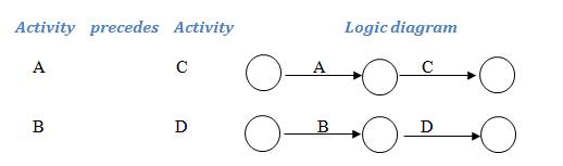
Consider the situation where you are given the following information about dependencies:
| Activity | precedes | Activity |
|---|---|---|
| A | C | |
| A B | D |
The only way to represent this in a conventional form is:
The problem is that this is incorrect. True activity A comes before activities C and D, but the diagram shows that activity C also needs activities A and B to be completed before it can begin, which is not correct. C only requires activity A to be finished.
Solution
A dummy activity is inserted to overcome the problem.
1. Draw the logic networks to represent the four different activities - i.e. ignore the duplicated activity when it is paired: in this case activity A
2: Use a dummy activity to join the two diagrams to produce the correct answer:
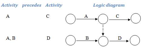

The direction of the arrow-head can be decided by thinking of rivers flowing and coalescing. Water flows from river A into both C and D, but water from B only flows into D - it cannot flow upstream into C.
Therefore, activity A flows into activities C and D. Activity B can only flow into activity D as up the dummy head points downwards. This satisfies the desired logic:
| Activity | precedes | Activity |
| A | C | |
| A B | D |
Activities A and B now operate in parallel; they are concurrent activities. Activity C follows only activity A, so can begin when A is finished, even if activity B is not complete. However, activity D follows activities A and B and cannot begin until both are finished.

Examiner's advice
You can recognise a dummy by the following rule:
You must construct a dummy when an activity precedes two different activities, but in only one case is it also linked with another activity.

Spot the Dummy!
You are provided with the following information on which you asked to construct a network diagram:
| Activity | precedes | Activity |
|---|---|---|
| A | B | |
| A | C | |
| B | D | |
| C | E | |
| D E | F | |
| D E | G | |
| F | H | |
| G H | I | |
| H | K | |
| I | J | |
| J | L | |
| K | L |
Have you spotted the dummy and know why? Follow the link below to check your understanding and logic:
Have you spotted the dummy?

Try drawing the entire network for this starting with individual logic diagrams.
In summary, the dummy is used as to maintain the correct logic in a set of dependencies, but does not create an additional activity. Remember that dummy activities take no time and use no resources:
Figure 4 Dummy activities

A dummy activity - Check your understanding
Explain the logic of the two diagrams above and how they differ.